Drawing & Plans
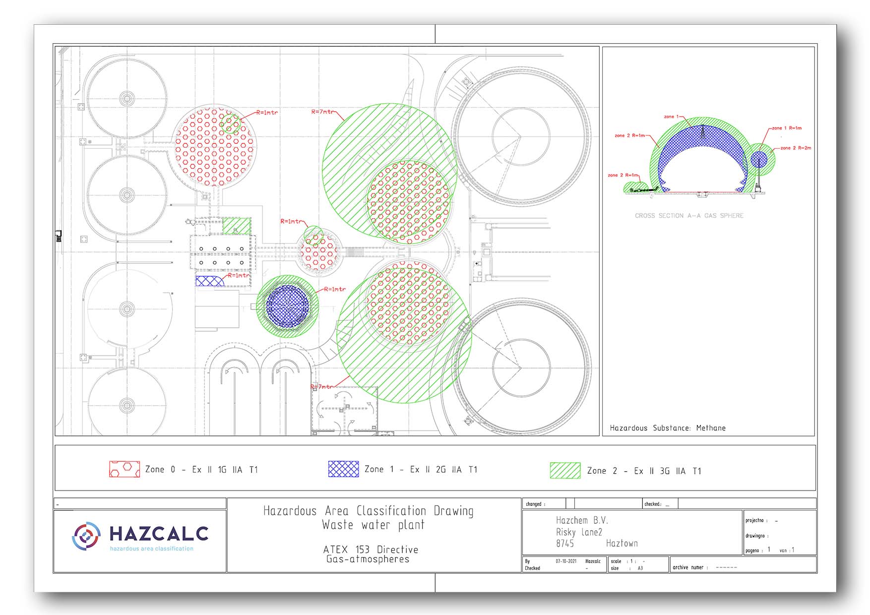
After performing hazardous area classification assessments the results must be presented and communicated to staff, personel, co-workers, contractors and other third parties in a Hazardous Area Classification Drawing. The nature of the zones and the extent of the zones must be presented in a clear way. This is an essential part of the Hazardous Classification (HAC) process.
The easiest way to create Hazardous Area Classification Drawings (HAC Drawings) is to use some kind of AutoCAD program, but it is certainly not essential. But, in CAD programs, the base drawings of a plant of factory can mostly be imported, so it is an easy way of working. Even pdf files or jpg and png files can be loaded into CAD. By creating an additional layer, the HAC zones can be drawn. It is a good practice to scale the zones correctly with the base-drawings.

Of course other programs can also be used. But beware that it is essential for good understanding of the zones, the Hazardous Area Classification Drawing must be as clear as possible. These days also 3D drawings are very helpfull with communicating about HAC. These drawings can be placed on boards near specific plant installations in order to clarify the zones and warn people.
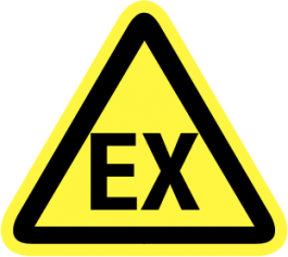
The minimum requirement for identifying zones in the field is the yellow Ex warning sign.
Rules for HAC drawings
In order to understand the Hazardous Area Classification Drawings (HAC drawings) and in order to communicate in a clear way, some rules are stated within the IEC Standard 60079-10-1:
Drawings should include plans and elevations or three dimensional presentation, as appropriate, which show both the type and extent of zones, equipment group, auto-ignition temperature or temperature class.
Where the topography of an area influences the extent of the zones, this should be documented
The documents should also include other relevant information such as:
- the location and identification of sources of release. For large and complex plants or
process areas it may not be practical to itemize or number all the sources of release in
which case simplified methods may be used; - the position of openings in buildings (for example, doors, windows and inlets and outlets
of air for ventilation).
The hazardous area classification symbols which are shown in the figure are the preferred ones. A symbol key shall always be provided on each drawing. Different symbols may be necessary where multiple equipment groups or temperature classes are required within the
same type of zone (for example, Zone 2 IIC T1 and Zone 2 IIA T3).
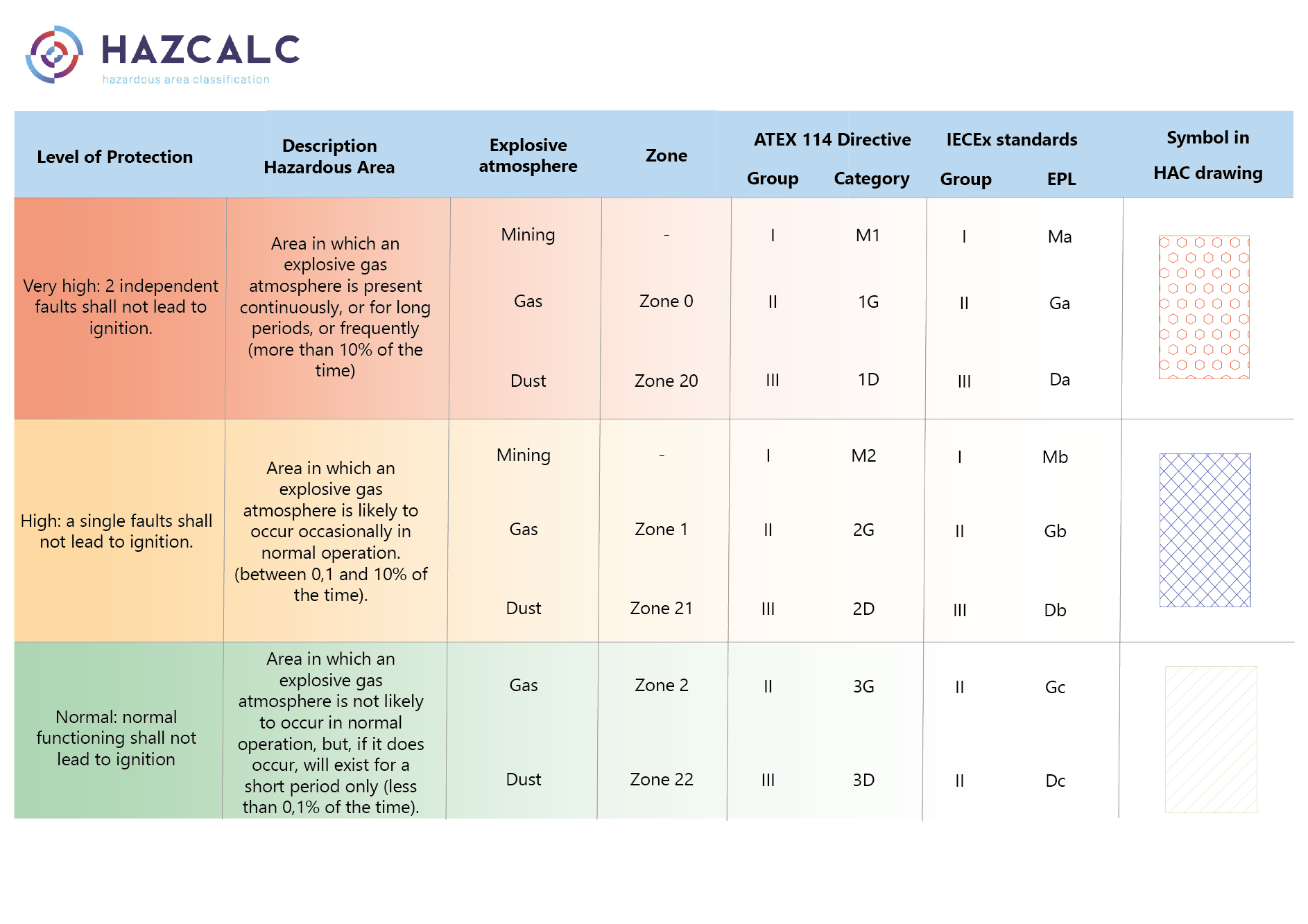
Relation between level of protection, area description, zones, category, EPL and drawing symbols
In the table below, the relation between the zone classification of areas and installation and the required equipment category (Cat.), Equipment Protection Levels (EPL) and drawing symbols, is specified.
See our page about Hazardous Areas and the selection of suitable components for more information about gasgroups and temperature classes.
Download Template for Hazardous Area Classification Drawing
An Autocad template for Hazardous Area Classification Drawing can be downloaded through the following link. The dwg file may be used for free.


